>> See also the Parallel Port OSDev Wiki Page <<
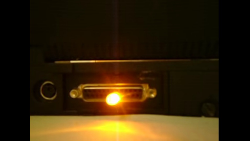
We just need to connect a LED between pins 9 and 2 of the LPT port on the motherboard.
Or as the pinout shows, between any of the orange (data) pins and the gray (ground, GND) pins. We have a total of 16 of those pins, 2 for each data bit to be able to plug the 2 wires in the LED or in other device.
Make sure to put the LED in its correct polarity, or just flip it, or it simply won't allow any electricity flow and won't turn on.
Usage of this program to turn on all of the 8 LEDs:
Code: Select all
lpthandler.exe 3bc 11111111

   or port 378
lpthandler.exe 378 11111111

   or port 278
lpthandler.exe 278 11111111
Code: Select all
lpthandler.exe 3bc 00000000

   or port 378
lpthandler.exe 378 00000000

   or port 278
lpthandler.exe 278 00000000
A 0 turns off and an 1 turns on.
Code: Select all
/*
 In short we only need:

  Out32(LPT_Base_Address+2, 0);          //Reset Control port with 0
  Out32(LPT_Base_Address,   0xFF-0x00);  //Write Data Port with any byte value
*/


//Here the LPT_Base_Address can be:
//
//          0x3BC -- LPT1
//          0x378 -- LPT1
//          0x278 -- LPT2
//          0x3BC -- LPT3
///

//We need to reset the Control Port writing a 0
//to configure their options, controlled for each of
//their bits:
///
  Out32(LPT_Base_Address+2, 0);

//Now send an value betwewen 0 and 255 to the data port:
///
  Out32(LPT_Base_Address, 0xFF-0x00);
YouTube video: Basics of Parallel Port Programming Under Windows, Part 1 of 2
YouTube video: Basics of Parallel Port Programming Under Windows, Part 2 of 2

>> Watch the Code Recording for lpthandler.c <<

The first thing is to get the code and binary for inpout32.dll for general low-level access under Windows:
inpout32_source_and_bins.zip [Mirror 1]
inpout32_source_and_bins.zip [Mirror 2]
Then we need what I/O addresses the parallel port has. The I/O ports are like memory addresses that range from 0 to 65535. To each of those addresses, we can send 1, 2 or 4 at a time, or we can receive 1, 2 or 4 bytes at a time. By now we just need to send 1 byte at a time.
LPT1 is at port (0x378, 378h)(888 decimal) or (0x3BC, 3BCh)(956 decimal).
LPT2 is at port (0x278, 278h)(632 decimal).
LPT3 is at port (0x3BC, 3BCh)(956 decimal).
The parallel port is an 8-bit peripheral, so it uses 8 data pins to hold the 8 bits of each byte (since it uses parallel, simultaneous signals), and those are the pins that we will manipulate by turning them on or off each time we write the data port, for instance, at port 0x378 (The Orange Pins, from 2 to 9):
Female Parallel Connector, at the Motherboard:

Now we need to use typedef short _stdcall (*_Out32)(short portaddr, short value), which comes from the inpout32.dll and hwinterface.sys.
Something like this:
Code: Select all
Out32(378h, 255-0);
The full source code is as follows:
Code: Select all
//NOTE: Compile with GCC under MinGW.
//
// gcc lpthandler.c -o lpthandler.exe
//
//Usage:
// lpthandler.exe LPT_Port Byte_Bit_Data
//
// LPT_Port:
//  - can be 3bc, 378 or 278
//
// Byte_Bit_Data:
//  - can range from 00000000 to 11111111 (written like that, in binary).
//    Every bit controls one of 8 LEDs.
//
// LEDs are connected between DATA and GROUND lines.
// DATA to GROUND lines are connected like this, for pins:
//
// DATA is + and GROUND is -
//
//  2-18
//  3-19
//  4-20
//  5-21
//  6-22
//  7-23
//  8-24
//  9-25
//
// Remember to set the parallel ports as Standard/Normal in the BIOS
// to ensure proper working of the basics with this program.
///

#include <stdio.h>
#include <windows.h>

typedef short _stdcall (*_Out32)(short portaddr, short value);
typedef short _stdcall (*_Inp32)(short portaddr);

int main(int argc, char *argv[])
{
 HINSTANCE INPOUT32_DLL_Handle;
 _Inp32 Inp32;
 _Out32 Out32;


 //Load the inpout32.dll library. It's also associated
 //with hwinterface.sys, but it should open it by itself:
 ///
  INPOUT32_DLL_Handle=LoadLibrary("inpout32.dll");
  if(INPOUT32_DLL_Handle == NULL)
  {
   printf("LoadLibrary failed for inpout32.dll...\n\n");
   return -1;
  }


 //Get access to the Out32/Inp32 functions from inpout32.dll:
 ///
  Out32 = (_Out32)GetProcAddress(INPOUT32_DLL_Handle, "Out32");
  Inp32 = (_Inp32)GetProcAddress(INPOUT32_DLL_Handle, "Inp32");

 //NOTE: The following two lines are the actual logic of the program
 //      and are at the top of importance and the program's key logic.
 //      Everything else could be considered API noise:

 //Configure the CONTROL Port with a 0 to sanitize the port state:
 ///
  Out32(strtol(argv[1],NULL,16)+2, 0);  //Bit 0: Strobe
                                        //Bit 1: Auto Line Feed
                                        //Bit 2: Initialize Printer
                                        //Bit 3: Select Printer
                                        //Bit 4: Enable IRQ Via Ack Line
                                        //Bit 5: Enable Bi-Directional Port
                                        //Bit 6: Unused
                                        //Bit 7: Unused


 //Write the Data port with the desired 8-bit value:
 ///
  Out32(strtol(argv[1],NULL,16), strtol(argv[2],NULL,2));


 //Unload our inpout32.dll library:
 ///
  FreeLibrary(INPOUT32_DLL_Handle);

 return 0;
}

