Page 1 of 4

Concise Way to Describe Curved Surfaces

Posted: Fri Jun 26, 2015 6:27 pm
by Brendan
Hi,

I'm designing a native file format for my OS to describe monitors. I started this because "raw EDID" from the monitor is ugly (e.g. 3 different ways to describe video modes timings rather than a single consistent method); so that I could add missing information (e.g. sub-pixel format, etc); and so that users can override (correct, extend) the monitor's EDID (or even just provide it when the OS can't get it from the monitor). The general idea would be that (unless the monitor's description has been overridden) the OS gets the "vendor and product ID" fields from the monitor's EDID and uses it to find a file (in my format) that's used instead (and if no file exists, it auto-converts the raw EDID into my file format).

Then I started thinking about old CRT monitors and their "concave curve" screen. I was thinking that I could add a "concave" flag to my file format so that the video driver could compensate for the curvature in software to ensure that the image the user sees isn't distorted.

That's when I googled for "curved screen" and saw things like this:
Image

And like this:
Image

And like this:
Image

Obviously; a single "concave" flag isn't going to work well.

Now I'm looking for way to describe "non flat" monitors, that can handle arbitrary curves (maybe even including things like "S-bend with a twist!"); but doesn't consume a massive amount of space (e.g. "(X, Y , Z)" physical location data for each pixel) or involve overly complex mathematics if it can be avoided.

Has anyone got any ideas?


Thanks,

Brendan
Re: Concise Way to Describe Curved Surfaces

Posted: Fri Jun 26, 2015 8:13 pm
by SpyderTL
Maybe come up with a list of primitive shapes: rectangle, sphere, cylinder, etc. and take the Union of those shapes, and maybe more shapes for clipping. Then "project" the screen onto that object.

I'm not sure how to make it any easier, and still allow you to define "arbitrary" screen shapes.

Or how about a bitmap of "depth" from the closest point to the user's eyes?

Re: Concise Way to Describe Curved Surfaces

Posted: Fri Jun 26, 2015 9:51 pm
by azblue
Bezier curves would seem to be the best choice for most situations, though that 2nd one looks like it has a bit of a steep dropoff; I'm not sure how well they'd work with that.

https://en.wikipedia.org/wiki/B%C3%A9zier_curve

Re: Concise Way to Describe Curved Surfaces

Posted: Fri Jun 26, 2015 11:16 pm
by Brendan
Hi,
SpyderTL wrote:Maybe come up with a list of primitive shapes: rectangle, sphere, cylinder, etc. and take the Union of those shapes, and maybe more shapes for clipping. Then "project" the screen onto that object.
To accurately describe something like (e.g.) a parabolic curve I think this would just devolve into a large number of small rectangles; and/or I'd end up with 50 special cases to deal with.
SpyderTL wrote:I'm not sure how to make it any easier, and still allow you to define "arbitrary" screen shapes.

Or how about a bitmap of "depth" from the closest point to the user's eyes?
A bitmap of "depth" would work for well for concave parabolic monitors (e.g. where all points are at the same distance from the user's eye). For flat monitors it'd create distortion because the angle between adjacent pixels near the edge of the screen is smaller than the angle between adjacent pixels need the middle of the screen (it'd be "fish bowl" distortion, similar to the distortion you get from old "convex curve" CRT screens).

Further notes!

I think the video driver would end up using the information to generate a grid of "angle pairs". Imagine a line from the user's eye to the centre of the monitor; where each pixel has a "left/right of centre line" angle (azimuth) and an "above/below centre line" angle (altitude). For a flat screen these angles are non-linear. The angles would also depend on how the monitor is positioned relative to the user (especially when multiple monitors are involved).

With that in mind, my first thought was to store the grid directly in the monitor's description. The problem with that idea was/is it consumes far too much space to store the full grid; and because the angles that the video driver wants depends on how the monitor is positioned the data in the monitor's description couldn't be used "as is" without messy re-processing. My next though was to store an "(X, Y, Z) offset from centre" for each pixel; which makes it easier for driver to generate that "grid of angles", but makes the space consumed for the data much worse.

My current thoughts are to split the screen's pixels into a variable number of rectangles and have an "(X, Y, Z) offset from centre" for each rectangle corner; and use (simple linear) interpolation for pixels within each rectangle to determine its location from the rectangle's corners.

In that case, for a normal "2D flat rectangle" screen you'd have a single rectangle with 4 corners and 4 control points (and for "2D flat quadrilateral" screens it'd be the same). For a screen like the first and third picture above, you might split the screen into a "64 wide, 1 high" grid of rectangles, and have "(64+1)*(1+1) = 130" control points. For a screen like the second picture you might split the screen into a "1 wide, 128 high" grid of rectangles (more due to the sharper angle on the right), and have "(1+1)*(128+1) = 258" control points. For other cases (old convex CRT, concave parabolic, etc) you might split it into a "64 wide, 64 high" grid of rectangles, and have "(64+1)*(64+1) = 4225" control points.

That's still relatively large (e.g. 4225 control points with three 32-bit values per point adds up to about 50 KiB) for the worst cases; but the common cases (e.g. flat screens and the recent "concave curve" screens) don't need much data.

The next step would be to use something like tricubic interpolation (instead of simple linear interpolation) to get smooth curves out of the control points. I'm currently looking into this to determine how messy it gets.


Cheers,

Brendan

Re: Concise Way to Describe Curved Surfaces

Posted: Fri Jun 26, 2015 11:20 pm
by Brendan
Hi,
azblue wrote:Bezier curves would seem to be the best choice for most situations, though that 2nd one looks like it has a bit of a steep dropoff; I'm not sure how well they'd work with that.

https://en.wikipedia.org/wiki/B%C3%A9zier_curve
I looked at bezier curves. The main problem is that the curves don't go through the control points, which means that you can't take physical measurements (e.g. with a tape measure) to determine the control points.

A secondary problem is that my skill in mathematics isn't what it probably should be (and adapting 2D bezier into 3D makes my head hurt). ;)


Cheers,

Brendan

Re: Concise Way to Describe Curved Surfaces

Posted: Sat Jun 27, 2015 1:13 am
by Rusky
Catmull-Rom splines do go through their control points, if you don't mind doing a bit of math.

I'm not sure screen curvature really needs to be handled, though- all the example images in your first post handle it by designing the curve to avoid needing any change in the software, and CRT monitors are pretty irrelevant at this point.

Re: Concise Way to Describe Curved Surfaces

Posted: Sat Jun 27, 2015 1:27 am
by alexfru
Brendan wrote: Then I started thinking about old CRT monitors and their "concave curve" screen. I was thinking that I could add a "concave" flag to my file format so that the video driver could compensate for the curvature in software to ensure that the image the user sees isn't distorted.
...
Now I'm looking for way to describe "non flat" monitors, that can handle arbitrary curves (maybe even including things like "S-bend with a twist!"); but doesn't consume a massive amount of space (e.g. "(X, Y , Z)" physical location data for each pixel) or involve overly complex mathematics if it can be avoided.
There's a little problem here. In order to compensate for the curvature you need to know the position (3d) of the viewer relative to the display. For some curved surfaces and viewer positions there's no way to compensate because some part of the screen can be occluded by another, just like with old CRT-based TVs and the watch and the cell phone on the pics above.

And even if you attempt to compensate, are you going to compensate for the "current window", possibly making some of its background (other windows) obscured on varying ways, or the whole screen, possibly cropping or scaling down to fit the screen, possibly making it ugly or to small?
Brendan wrote: which means that you can't take physical measurements (e.g. with a tape measure)
This (manual measurement) is likely an inadequate approach. First, it isn't going to capture the surface details or the locations, orientations and sizes of the pixels. Second, you don't want to ask the user to perform such measurement.
Brendan wrote: A secondary problem is that my skill in mathematics isn't what it probably should be (and adapting 2D bezier into 3D makes my head hurt).
I probably wouldn't bother trying to make a generic solution to a problem that isn't even well defined and formulated.

Re: Concise Way to Describe Curved Surfaces

Posted: Sat Jun 27, 2015 1:33 am
by Candy
+1 on using catmull-rom. As they go through their control points, they generalize completely on any arbitrary type T to spline - I've got a templated version working on camera's, consisting of a vector and a quaternion, as well as colors, vectors and floats. And probably anything else you put in. I've pasted this one below so you can try it out - public domain release.

http://pastebin.com/yJjiizaM

There's catmullrom - either 4 param for a single bit, or a std::vector for a longer spline - and catmullromdt for its derivate. Then there's catmullrom2, which I've modified to be second-derivate continuous too, and catmullrom2dt and catmullrom2dt2 for its first and second derivate. I'd use the first.

It probably doesn't match quite as nicely to the Galaxy Edge screen, but the rest should be easy enough.

Re: Concise Way to Describe Curved Surfaces

Posted: Sat Jun 27, 2015 1:40 am
by SpyderTL
If the point of this data is to "adjust" an image so that it appears the exact same on all monitor screen shapes, then I think a depth bitmap is a good choice.

Essentially, if you imagine a clear piece of plastic, held up in front of your eyes, that you could bend into some shape, and see through to the other side. Then you could take a snapshot of what you see on that plastic from that angle. Then you "unroll" or flatten the plastic to a single plain. The image would then (possibly) be distorted.

But placing that plastic on your curved monitor would reverse the distortion, giving you the original image. I assume this is essentially what you are going for.

So the key would be to "project" the flat image you are trying to display onto this curved sheet of plastic. For each physical pixel on the screen, you'd need to know where the flat image "intersects" with the curved piece of plastic as the light travels from the "object" to the user's eye.

You've got a similar problem to what those 3D sidewalk chalk artists have.

http://www.imagekb.com/3d-sidewalk-chalk-art-wrong-view

Another thing to consider is that, technically, you can only perspective correct for one eye of the other, but not both. All of this effort may end up being futile once you see the end result, and it becomes immediately obvious that the image is distorted because the image only looks flat if you close one eye. There's almost no way to know unless you go through the effort to make it work, and see for yourself if it actually looks convincing or not.

You may want to experiment by taking a picture, and wrapping it around a cylinder and taking a picture of that, and printing that picture out and bending it in the opposite direction and seeing if it appears as if the original picture is floating behind the page. Or something. :)

EDIT: Regardless of which data format you decide to use, you can probably save some space by simply storing the information for one half, or one quadrant of the screen, since virtually all screens will have identical surface contour vertically and horizontally.

Also, I imagine that flexible screens will be available in the fairly near future. Just something to keep in mind.

Re: Concise Way to Describe Curved Surfaces

Posted: Sat Jun 27, 2015 4:04 am
by Brendan
Hi,
Rusky wrote:Catmull-Rom splines do go through their control points, if you don't mind doing a bit of math.
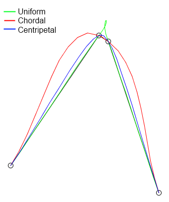
I looked at Catmull-Rom splines, and couldn't figure out how to handle the first and last points correctly. Example code I looked at "invented" new end points (e.g. created a "point[0]" by extrapolating from "point[1]" and "point[2]") which mostly causes the curve at the start and end to be wrong.

For example:
Image

For "chordal" it's easy to see the problem - the fake/hidden points means that the line begins and ends at the wrong angle from the first and last real point. For "centripedal" it's less obvious, but the problem is still there.
Rusky wrote:I'm not sure screen curvature really needs to be handled, though- all the example images in your first post handle it by designing the curve to avoid needing any change in the software, and CRT monitors are pretty irrelevant at this point.
For 3D games; if you don't correct for curvature it's just plain broken - horizontal lines near the top & bottom of the screen will look bent and not straight, and things near the left/right edges will be drawn "less tall" than they should. To understand this find a 3D game that has square room, look directly at a corner and measure from floor to ceiling at that corner, then rotate the camera so that the corner is near the edge of the screen and do the "floor to ceiling" measurement again - you'll find it's shorter now, which is correct for flat screen (because for flat screens, the edges of the screen are further from your eye than the centre). For curved screen (e.g. where the distance from eye to screen is constant) that "floor to ceiling" measurement should remain constant as you turn the camera left/right. For "camera spinning in a square room" it'd end up looking like the room is expanding/contracting while you spin..

For typical "desktop full of windows", software that fails to correct for curvature would be much easier to get used to, but only because windows are normally drawn "flat" and it's easy enough to get used to curved windows. It's still wrong though, and if you're planning to have more 3D elements in your GUI (windows drawn at angles, dynamic lighting/shadows, etc) it ends up being the same problem as 3D games.


Cheers,

Brendan

Re: Concise Way to Describe Curved Surfaces

Posted: Sat Jun 27, 2015 4:17 am
by Candy
I looked at Catmull-Rom splines, and couldn't figure out how to handle the first and last points correctly. Example code I looked at "invented" new end points (e.g. created a "point[0]" by extrapolating from "point[1]" and "point[2]") which mostly causes the curve at the start and end to be wrong.
The point behind the first and last point is that they determine the derivative at the actual last and first point. The derivate at P1 is P2-P0, the derivative at P2 is P3-P1. You can then determine what derivative you want at P1 by calculating P0 such that the derivative is correct (and same for P3).

Re: Concise Way to Describe Curved Surfaces

Posted: Sat Jun 27, 2015 4:34 am
by Combuster
The problem with any single curve is that it can't convey discontinuous curvatures, such as flat objects with distinct corners, and you need multiple curves for that, resulting in a spline. For all the examples posted here, you can always reduce this to a list of cubic equations, to be selected based on the input coordinate. (e.g. 0-0.8 uses equation a, 0.8-0.9 uses equation b to go around the corner, and 0.9-1.0 uses equation c for the side of the screen)

If you then use a traditional B-spline or a catmullrom for the actual drawing, that is just choosing a method of inputting that data with visual aids. In the end, what you probably want is some code that finds a through d in fn = ax³+bx²+cx+d where fn(0) = starting point, fn(1) = end point, fn'(0) = starting direction and fn'(1) = ending direction. It's on the easy end of the spectrum for those mathematically inclined, but it's also often good enough to scare people away.

And even though catmullrom and all the other cardinal splines have the property of each control point actually being touched, they are a liability for various other things. For instance, to make a single corner in the screen, you will want a polygon piece that's exactly horizontally oriented on one side, and exactly vertically oriented on the other side. That means that the control point immediately before and after of the starting point must be horizontal respective to each other, and that the control points immediately before and after the end point are vertical in respect to each other. That leads to a paradoxal situation (taking your middle photo as an example):

Code: Select all

               ^ A must be on this line to avoid bulges :(
               ·
A**/ /*****B** ······> C must be on this line to avoid bulges :(
              * 
               *
               C
               *
               *
               D
In addition, all the stock B-splines fail if you also want to be able to map actual pixel coordinates correctly, because the plotting coordinate will give the same amount of pixels in A-B as there are in B-C and C-D, or basically, there would mathematically be more pixels in the little screen corner than there is on the primary screen.
Both problems can be fixed by actually specifying the "time" coordinate per spline point, as well as the actual mapping angle. Of course, you can still use the cardinal/catmull-rom equations to suggest initial angles for you and it's probably good to get away with in a fair few cases. You can segment the actual screen in colours to live aid in selecting the actual pixel coordinates, but by now your base mathematical model has already become a non-uniform B-spline

There's one problem left: up to now there have only been polynomial splines, and they can't do circles or ellipses, and you will get to see them in practice: B-C above probably is a quarter circle rather than a parabola. To fix that, you need NURBS, and I can imagine a significant bigger portion of programmers running away at this moment. :twisted:


Brendan wrote:I looked at Catmull-Rom splines, and couldn't figure out how to handle the first and last points correctly.
One of the most common conventions is that the "missing" neighbours of the start and end points are at the same location as the start and end points themselves. And as you have shown, there are sufficient other options and in the end you might just want to deal with it like the problem sketch above.

Re: Concise Way to Describe Curved Surfaces

Posted: Sat Jun 27, 2015 5:19 am
by Brendan
Hi,
alexfru wrote:There's a little problem here. In order to compensate for the curvature you need to know the position (3d) of the viewer relative to the display.
Yes; but I was planning to do that anyway. More specifically I'm planning to eventually have some sort of utility that shows the user their monitors inside a little virtual 3D world, and lets the user drag/move them around to describe where all the monitors are; not just so that the OS knows where the monitors are in relation to the user, but also so that the OS knows where monitors are in relation to other monitors.
alexfru wrote:For some curved surfaces and viewer positions there's no way to compensate because some part of the screen can be occluded by another, just like with old CRT-based TVs and the watch and the cell phone on the pics above.
The video driver can simply skip any occluded areas.
alexfru wrote:And even if you attempt to compensate, are you going to compensate for the "current window", possibly making some of its background (other windows) obscured on varying ways, or the whole screen, possibly cropping or scaling down to fit the screen, possibly making it ugly or to small?
Imagine you're sitting inside a sphere (let's call that sphere "the real world"), where the monitors (regardless of how many monitors of which shape/s or sizes you have, or where they are around you) are holes in the sphere that let you see into a virtual world. That virtual world might have applications floating around, and those applications might float past the holes (monitors) so that you see them.

It's not really about compensating a window or an individual screen, but more like punching nice "distortion free" holes in reality.

alexfru wrote:
Brendan wrote:which means that you can't take physical measurements (e.g. with a tape measure)
This (manual measurement) is likely an inadequate approach. First, it isn't going to capture the surface details or the locations, orientations and sizes of the pixels. Second, you don't want to ask the user to perform such measurement.
You're right - I don't really want to ask each user to perform measurements; but someone somewhere would need to create the necessary data. Ideally it'd be the hardware manufacturer, but it's far more likely that a user is going to have to do it and send the resulting file to me so that I can include it with the rest of the OS (where it'll be used automatically whenever the OS detects that monitor, and no other user will need to create the data again).


Cheers,

Brendan

Re: Concise Way to Describe Curved Surfaces

Posted: Sat Jun 27, 2015 5:54 am
by embryo2
Brendan wrote:I was thinking that I could add a "concave" flag to my file format so that the video driver could compensate for the curvature in software to ensure that the image the user sees isn't distorted.

... Some pictures here ...

Obviously; a single "concave" flag isn't going to work well.

Now I'm looking for way to describe "non flat" monitors, that can handle arbitrary curves
First it is recommended to determine what do you actually need. For what purpose you need the way to describe the curvature? If it should look "so that the video driver could compensate for the curvature in software to ensure that the image the user sees isn't distorted" then the next question is - what kind of distortions you are trying to fight? As I can see from another your message you do not like the look of a room if viewed on a big monitor. But exactly the same distortion occurs when a person looks at a fence from some small distance. Such distortion is called perspective. The nearest edge of the cube on that picture looks bigger than other edges just because of the perspective effect. In photography for short focused lens to give straight lines some compensation is added when the lens are designed, but as a result proportions of objects in the resulting picture corners became distorted. It means that you have to choose what kind of distortion you prefer to fight for the first place.

I suppose that your thought was about some possible distortions that potentially can look ugly. But in fact if you will play with different displays the actual distortion can look pretty much acceptable. Then I recommend you to model the situation on a flat screen of a big size. First, for it to be valid you need to be sure that the distance from eyes to the screen is much less than the screen's diagonal (so the really big display is preferable, like those with 40-50 inches on board). Next you need to find some formulas that compensate the perspective effect and apply them to the original test rectangle that you can look at to be able to assess the distortion importance. Next draw the resulting rectangle (or more exactly - the resulting shape after compensation transformations applied) on a screen and compare your visual impression with the straight rectangle. May be after such testing your assumptions about distortion importance will be corrected seriously. But if you would see something that you think really should be corrected, then it will be not very complex if we remember that you already managed to work with perspective compensation math.

And about the "way to describe...". The minimal memory is required for the formula based solution, also some processing can be (sometimes) simplified if you have a formula. But the choice of the formula can be a bit challenging (as we can see above). If you concentrate on a simple situation with 2D only curvature (which often is the case for modern displays) and forget about eye positioning compensation then may be just one formula of an ellipse (or even a circle) can serve you, or the ellipse can be combined with flat surface at some point, like on your image#2. The spline based description is a bit more complex, but because it suits the need for interpolation of experimentally found data you can use it for the data gathered after some manual display measurement. But the transform of spline curves in 3D space, that compensate for some tricky distortions is relatively complex. May be in 2D situation it is possible to find some relatively simple transform, but curvature almost often requires some tricky math.

And finally, as I see from your last post you are trying to implement some virtual reality engine, so it is really highly recommended to consider some math-related reading about 3D modeling and transformations.

Re: Concise Way to Describe Curved Surfaces

Posted: Sat Jun 27, 2015 7:59 am
by Owen
Brendan,

I'm not quite sure of the correct approach for this (unless you want to do the scary thing of NURBS, apparently), but while you considered traditional curved screens there, I can think of another class of effectively curved screens to consider, ones that look like this:

Image

(For what its' worth, the correction information for the Oculus Rifts are stored as code - specifically, a fragment shader)